August 14, 2023 feature
This article has been reviewed according to Science X's editorial process and policies. Editors have highlighted the following attributes while ensuring the content's credibility:
fact-checked
peer-reviewed publication
trusted source
proofread
Uncovering the local atomic structure of zeolite using optimum bright-field scanning transmission electron microscopy

Zeolites have unique porous atomic structures and are useful as catalysts, ion exchangers and molecular sieves. It is difficult to directly observe the local atomic structures of the material via electron microscopy due to low electron irradiation resistance. As a result, the fundamental property-structure relationships of the constructs remain unclear.
Recent developments of a low-electron dose imaging method known as optimum bright-field scanning transmission electron microscopy (OBF STEM) offers a method to reconstruct images with a high signal-to-noise ratio with high dose efficiency.
In this study, Kousuke Ooe and a team of scientists in engineering and nanoscience at the University of Tokyo and the Japan Fine Ceramics Center performed low-dose atomic resolution observations with the method to visualize atomic sites and their frameworks between two types of zeolites. The scientists observed the complex atomic structure of the twin-boundaries in a faujasite-type (FAU) zeolite to facilitate the characterization of local atomic structures across many electron beam-sensitive materials.
Analyzing zeolites in the materials lab
Zeolites are porous materials that are regularly arranged in nanosized pores suited for a variety of applications during catalysis, gas separation and ion exchange. The material properties are closely related to the pore geometry allowing subsequent interactions with adsorbed guest molecules and ions. Researchers have thus far used diffractometric methods to analyze the structure of zeolites.
For example, materials scientists have demonstrated scanning electron microscopy to be a powerful method to analyze local structures to observe the atomic arrangement of electron-resistant materials at the sub-angstrom level. Zeolites are, however, more electron-beam sensitive when compared to other organic materials thereby limiting electron microscopy-based observations due to electron irradiation.
Optimum bright-field scanning transmission electron microscopy (OBF/STEM)
In 1958, materials scientist J. W. Menter observed zeolites using a high-resolution transmission electron microscope to report a lattice resolution of 14 Angstrom. Images of the zeolite framework substantially improved via advanced imaging in the 1990s, although it remained challenging to observe the atomic sites in the materials.
Recent advances of scanning transmission electron microscopy (STEM) electron detectors have led to more advanced imaging methods such as the optimum bright-field (OBF) STEM method to observe atomic structures at the highest signal-to-noise ratio to obtain atomic-resolution images in real-time.
In this work, Ooe and colleagues used real-time OBF imaging to determine the architecture of zeolites at subangstrom resolution. The outcomes emphasized the capacity of advanced electron microscopy to characterize the local structure of beam-sensitive materials.

Direct imaging of atomic structures in zeolites: Real-time OBF imaging vs. STEM imaging
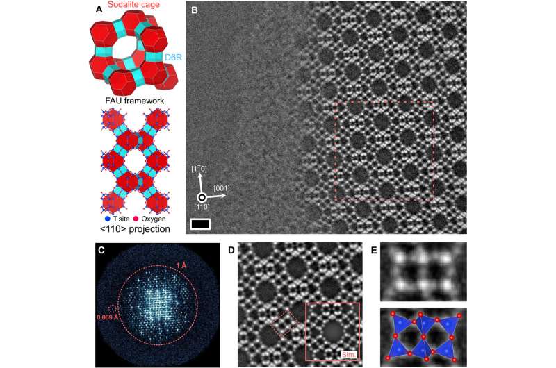
The zeolite framework consisted of two building blocks—sodalite cages and double 6-membered rings. Using real-time optimum bright-field (OBF) imaging, the team detected the framework of the material and used an electron probe current of 0.5 pico-angstrom to prevent any beam-related damage in order to analyze the typical inorganic materials. They then compared the OBF images with other scanning transmission electron microscopy images obtained under similar dose conditions.
The existing STEM methods showed a basic structure of the material framework; however, atomic structure analysis with this method was challenging due to a low current dosage. In contrast, the OBF images offered a more reliable and interpretable image contrast with higher dose efficiency.
Direct observation of the twin boundary
The research team used the optimum bright-field method to examine the atomic structure of a twin boundary in the zeolite structure. The framework was made by cubic stacking a layered structure unit known as a "faujasite sheet." The outcomes of imaging with OBF showed a power spectrum of the image with an information transfer beyond 1 Angstrom. The low-dose light-element imaging with OBF STEM offered a better alternative to analyze the structure of zeolites including the local change of symmetry.
Ooe and colleagues conducted density functional theory calculations to examine the stability of the twin boundary structure where the experimental image agreed with its simulated counterpart.
The team applied the method to a different type of zeolite sample to show how the typical silicon aluminum ratio of these samples are crucial to the material properties to influence the adherence of ions and molecules. When they applied the method to a sodium-based zeolite sample for atomic observations, the outcomes facilitated the conception of extra cation sites with low occupancy in the zeolitic framework.
Outlook
In this way, Kousuke Ooe and colleagues devised a dose-efficient scanning transmission electron microscopy imaging method known as "optimum bright field scanning transmission electron microscopy" (OBF-STEM) for low-dose atomic resolution imaging. The team showed how the method directly revealed the atomic structures of all elements in a faujasite-type zeolite material—a known beam-sensitive material with subangstrom space resolution.
The method can be used to detect lattice defects in the material framework. They visualized the atomic sites in the framework alongside its captured cations to obtain results that were in quantitative agreement with image simulations. The method is applicable across beam-sensitive materials beyond zeolites to characterize the local atomic structure and study the structure-property relationships of sensitive materials.
More information: Kousuke Ooe et al, Direct imaging of local atomic structures in zeolite using optimum bright-field scanning transmission electron microscopy, Science Advances (2023). DOI: 10.1126/sciadv.adf6865
L. A. Bursill et al, Zeolitic structures as revealed by high-resolution electron microscopy, Nature (2004). DOI: 10.1038/286111a0
Journal information: Science Advances , Nature
© 2023 Science X Network


