February 21, 2022 feature
Mechanical metamaterials: Toughness and design criteria
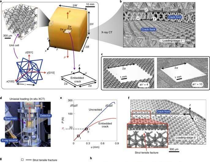
Mechanical metamaterials are an emerging class of materials primarily governed by their architecture to create lightweight materials with extreme mechanical properties. The functionality of such materials is limited by their tolerance to damage and defects, better known as "fracture toughness." Materials scientists credit the difficulty in part to the manufacture and characterization of a large number of unit cells. In a recent report now published on Nature Materials, Angkur Jyoti Dipanka Shaikeea and a team of scientists in engineering and metamaterials at the University of Cambridge U.K., and the University of California, Los Angeles, U.S., combined numerical and asymptotic analyses to extend the ideas of elastic fracture mechanics to mechanical 3D metamaterials and developed a design protocol to form optimally robust discrete solids.
The evolution of materials
The evolution of materials engineering has led to the development of a range of material properties with unique combinations, and the material property space can be expanded by introducing new alloys and new microstructures. Advances in additive manufacture have allowed intriguingly accurate small-scale, periodic and functionally graded architectures that can be formed into large networks to create man-made materials on the macroscopic scale known as metamaterials, alongside mechanical metamaterials more distinctly defined by their structure rather than composition.
Three-dimensional (3D) micro- and nano-lattices are a promising class of low-density materials with numerous applications including thermal insulation and energy absorption, with remarkable mechanical and functional properties. These functionalities are governed by the parent material and their architecture, known as mechanical metamaterials. Researchers have used additive manufacturing methods, including projection microstereolithography and two-photon lithography to form polymeric, metallic and ceramic metamaterials.
Primary author Angkur Shaikeea is a Cambridge India Ramanujan Scholar; he joined Cambridge for his Ph.D. with Professor Vikram Deshpande, who is an eminent scholar in mechanics of solids. Shaikeea is currently the Ashby Research Fellow in the Engineering department at Cambridge. The team of scientists have formed key collaborations with another leading team at the metamaterial fabrication lab of Dr. Xiaoyu Rayne Zheng at the University of California, Los Angeles, U.S., to realize the outcomes of this research. In this work, Shaikeea et al. used a stretch-dominated metamaterial made of a network of struts to form an octet-truss. The team developed the large 3D specimens containing nearly 10 million periodic cells and cell sizes as small as 150 µm via large-area projection microstereolithography to form each layer through a continuously moving projection via subsections.
Cutting-edge experimental methods
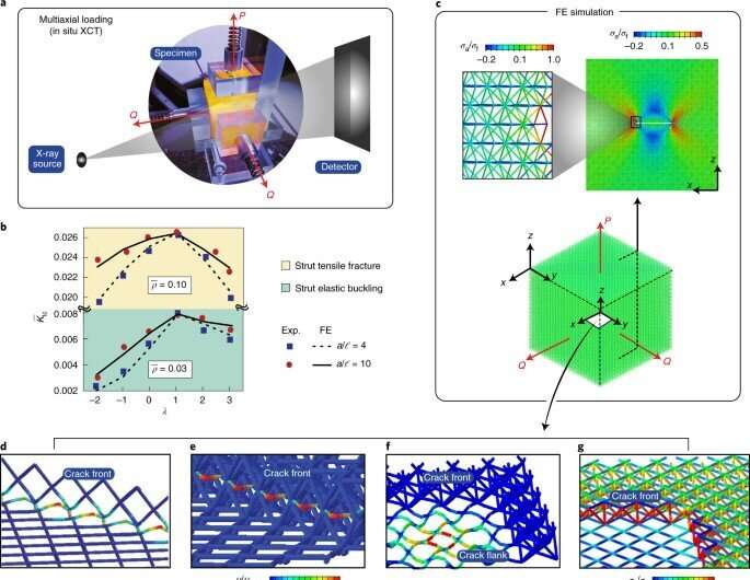
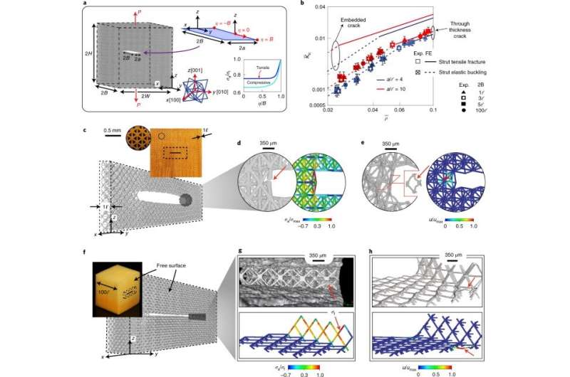
The experimental system allowed the scientists to manufacture samples with embedded cracks to perform a range of valid fracture toughness measurements. Using in situ X-ray computed tomography and large-scale numerical simulations, the team characterized fracture mechanisms across a range of specimen densities, parent materials, cell sizes and crack sizes, including loading configurations. Shaikeea described the concept of architected metamaterials as "a rapidly proliferating engineering material suited for a wide range of applications, although such materials are limited in structural applications simply since, no engineering material can find application without a clear understanding of defect and damage tolerance." He explained that "this was highlighted thus far by a lack of experiments measuring the toughness in large 3D specimens."
To generate the required crack-tip K field for fracture toughness mechanisms, they formed the metamaterial specimen by using a large-area projection microstereolithography system. The method allowed printing of each layer via single projection to develop inhomogeneous material properties, although with enclosed heat in the central region. To overcome this, the team used a moving projection system for curing in subsections for reduced heat generation with enhanced dissipation, and increased printing area without sacrificing resolution.
The team combined the experimental setup with X-ray computed tomographic (XCT) observations and large-scale numerical simulations to characterize fracture mechanics of truss-based 3D metamaterials. Shaikeea notes the use of "XCT data as a major advancement for experimental mechanics in general." As a first step to characterize the fracture, they employed uniaxial tensile tests, and combined them with an in situ observation protocol. To develop a physical understanding of the observations, they performed finite element simulations for uniaxial and multiaxial loading cases and modeled every strut in the specimen.
Developing a design protocol: Fracture mechanism maps
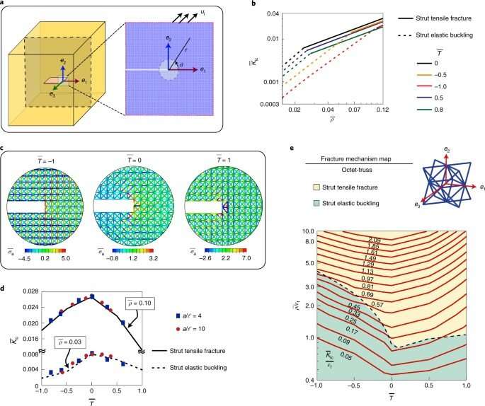
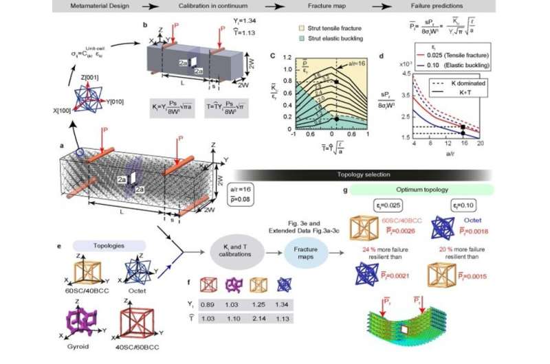
The team developed a protocol to select the optimal topology for a given application. They combined calibration factors with metamaterial microstructural parameters and constituent material properties to form "fracture mechanism maps" to provide information on the failure mode and toughness of the metamaterial. By using fracture maps from different types of unit cell topology, they created topology selection maps to maximize toughness or failure loads, allowing researchers to select optimized metamaterial topologies based on various design parameters.
The procedure was independent of topology and is applicable for other classes of truss-based metamaterials. Such maps can be used by materials designers to identify failure in different applications at minimal computational cost, compared to modeling microstructural detail of the metamaterial. This setup can provide a materials selection protocol for mechanical metamaterials design, much like Ashby plots for materials selection in materials design with conventional materials.
Applications of the proposed framework
The researchers showed that the framework applies to any 3D metamaterial, regardless of its topology and constituent material properties. Further investigations will shed light on the types of constituent material behavior, including stress, which can influence qausibrittle materials. Many engineering materials are affected by strain rates and size effects, where materials that are brittle at bulk scale show improved ductility and toughness at sub-micron scales. The multiscale in situ characterization studies can help understand and predict mechanical properties of the metamaterials with features spanning several orders of magnitude.
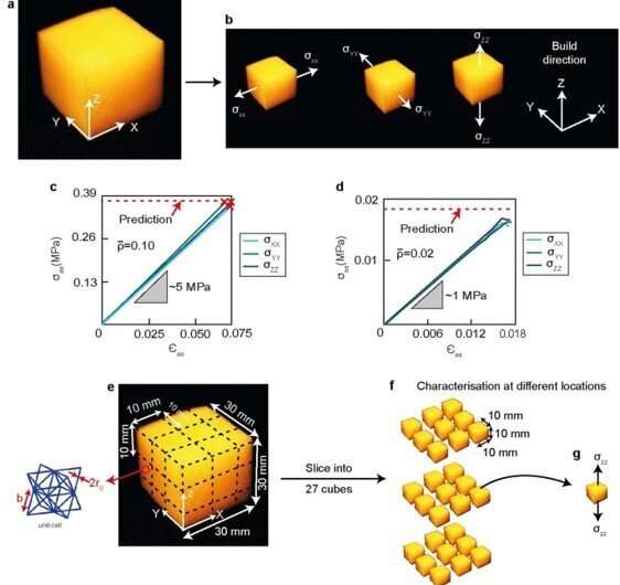
The work will inspire investigations of diverse metamaterial topologies including shell and plate lattices, non-uniform periodic arrangements including crystal-inspired architectures. Shaikeea highlights a key outcome of the study as "understanding T-stress and its effects in fracture mechanics of 3D architected solids."
Outlook
In this way, Angkur Jyoti Dipanka Shaikeea and colleagues developed a novel study as a milestone towards structural applications of mechanical metamaterials. The work will prompt materials scientists to revisit fundamental concepts of fracture in discrete solids, while providing a framework to form optimal metamaterials for specific applications. More research could be done to explore various topologies, material behaviors and size effects of metamaterials relative to mechanical characteristics of strength and toughness. The work has the potential to develop metamaterial selection maps and performance indices, much like Ashby plots for conventional materials, with profound impact on future mechanical studies.
More information: Angkur Jyoti Dipanka Shaikeea et al, The toughness of mechanical metamaterials, Nature Materials (2022). DOI: 10.1038/s41563-021-01182-1
A. Fleck et al, Micro-architectured materials: past, present and future, Proceedings of the Royal Society A: Mathematical, Physical and Engineering Sciences (2010). DOI: 10.1098/rspa.2010.0215
Journal information: Nature Materials
© 2022 Science X Network


