This article has been reviewed according to Science X's editorial process and policies. Editors have highlighted the following attributes while ensuring the content's credibility:
fact-checked
proofread
Scientists study mode switching control for drag-free satellite based on region of attraction

In recent decades, drag-free satellites have been used in high-precision missions, such as testing the general relativity, verifying the geodetic and frame-dragging effects, measuring Earth's gravity field, etc. In space gravitational wave detection, drag-free satellites play an important role.
Previous research on the drag-free satellite has focused on the drag-free control algorithm. Nevertheless, science mode and nonscience mode have different control forces, sensor measurement range, measurement noise, and reaction force noise. Therefore, the different controllers for the capture control mode and the high-accuracy control mode of the test mass (TM) need to be designed.
However, it is easy to cause system instability or even uncontrollability when switching between different controllers. Research on the switching control between different modes is very important. In the drag-free satellite, there is little research on the switching control between different modes. Multi-degree of freedom strong coupling and controller saturation remains an urgent problem to be solved.
In a research paper recently published in Space: Science & Technology, researchers from Shanghai Institute of Satellite Engineering, China, Sun Yat-sen University, China, and Tohoku University, Japan, together propose a switching rule to improve the efficiency and stability of the mode switching process for the drag-free satellite system after TM releases.
First, authors give the reference coordinate system and dynamics models. In space gravitational wave detection, the drag-free satellite has 2 cubic TMs with an angle of 60° between them (see Fig. 1A). Three reference coordinate systems are used (see Fig. 1B). The inertial reference coordinate system is the Earth mean equator J2000 coordinates.
Orbit Coordinate System (OCS) originates at the satellite mass center Or on the ideal orbit, with zr-axis pointing from Earth's mass center to the satellite's mass center and the xr-axis perpendicular to the zr-axis in the orbit plane and coinciding with the velocity.
Cavity Coordinate System (CCS) originates at the center of the satellite cavity, with xi-axis directing toward the laser link and zi-axis perpendicular to the xi-axis in the orbital plane. As for dynamics and motion models, the motion model of the satellite relative to the ideal orbit is established in the inertial coordinates, considering the error vector r = [x, y, z]T of the satellite relative to the ideal orbit, the control vector us = [usx, usy, usz]T acting on the satellite, and the interference vector ds = [dsx, dsy, dsz]T acting on the satellite.
The motion model of the TM relative to the cavity is given in OCS, with the position vector ρi = [xi, yi, zi]T from the cavity center to the TM's mass center, the vector cai = [caix, caiy, caiz]T from the satellite's mass center to the cavity center, the control vector ui = [uix, uiy, uiz]T acting on the TM, and the interference vector di = [dix, diy, diz]T acting on the TM. Besides, the solar radiation pressure, the reaction force, the position measurement noise, and the reaction force noise are formulated.
Then, authors investigate the controller design, and analyze the stability in view of the Lyapunov function and the region of attraction. Unlike traditional satellite control systems, the drag-free satellite's control system includes the inner loop and the outer loop (see Fig. 2).

The inner loop is used to control the TM including the TM's capture control and the TM's high-precision control, while the outer loop is used to control the satellite. For the drag-free satellite, the PID control law us is designed and the thruster model Pm is obtained by polynomial fitting with the anode voltage and the mass-flow rate. For the TM's capture controller, the sliding mode control is selected due to its good robustness.
According to the state equation of the TM movement model relative to the cavity and the exponential approach law, the 3-axis control law ui of the TM is obtained. After capture, the H∞ mixed-sensitivity controller is designed to improve the control accuracy and reduce the noise effect.
By linearizing the state equation of the TM movement model and decoupling the system with the inverse matrix of the plant, the mixed-sensitivity problem is expressed as an optimization problem and the system control law is obtained. The sliding mode controller (i.e., subsystem 1) and the H∞ mixed-sensitivity controller (i.e., subsystem 2) can be respectively proved stable via their the Lyapunov function Vt1 and Vt2.
Furthermore, letting Vt1(tf) > Vt2(tf) where tf is the switching time, the switching system is global stable according to the piecewise Lyapunov function method. Although the system satisfies the global stability requirements, it cannot guarantee the local stability of the nonlinear system after switching. In order to avoid system instability, Subsystem 1 is required to switch after entering the ROA of Subsystem 2.
The ROA is defined as Ω(ρ,t) = {Xh ∊ Rn | 0 ≤ Vh(Xh,t) ≤ ρ(t)} where Rn is the Euclidean space, Vh(Xh,t) is the Lyapunov function of the nonlinear Subsystem 2, and ρ(t) is the continuously differentiable function. The sum of squares (SOS) method is used to calculate the ROA of Subsystem 2. Through calculation, the ROA is Vt2 ≤ 3.129×10⁻¹⁵, and Vt1 is made greater than 3.129×10⁻¹⁵ at time tf, which ensures the system is globally stable.
Finally, authors show the numerical results and draw the conclusion. To test the performance of the switching control method, the numerical simulation is carried out. In simulation, the initial states of the TM relative to the cavity are (200 μm, 5 μm/s, 200 μm, 5 μm/s, 200 μm, 5 μm/s). The initial relative states of the satellite are (0, 0, 0, 0, 0, 0).
The position coordinates of the TM1 and TM2 are (0.3 m, 0, 0) and (−0.3 m, 0, 0) in OCS, respectively. The maximum root mean square voltage of the Subsystem 1 and Subsystem 2 are 96 and 7 V, respectively. Results show that the relative motion errors of the satellite on the 3 axes are controlled within 0.1 nm and the control force is always within the thrust range, and there is no saturation.
-
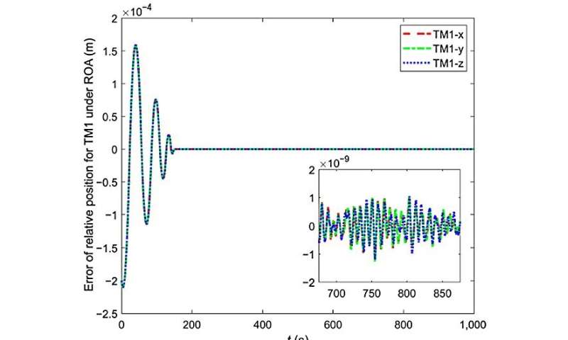
Fig. 7 The relative motion error of TM1 under the switching rule of the ROA and the non-ROA. Credit: Space: Science & Technology -
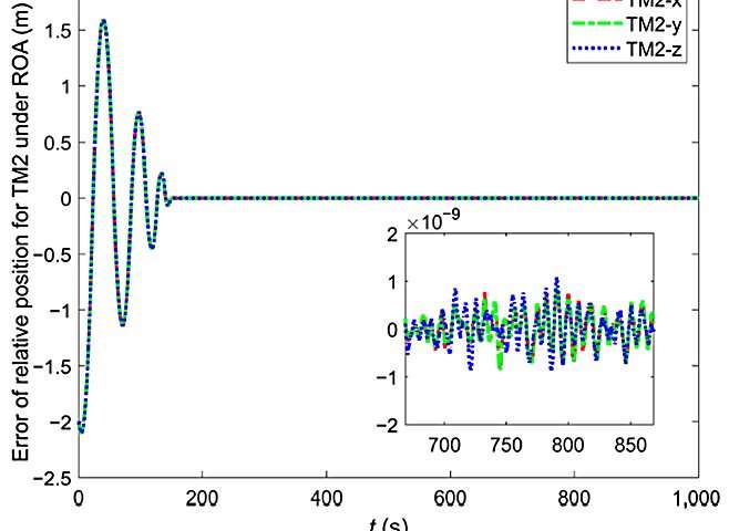
Fig. 8 The relative motion error of TM2 under the switching rule of the ROA and the non-ROA. Credit: Space: Science & Technology
To study the performance of the proposed switching rule, the control errors of TM1 and TM2 under the switching rule of the ROA and the non-ROA are compared and analyzed, as shown in Figs. 7 and 8. It can be seen that Subsystem 1 is switched to Subsystem 2 under the constraints of the switching rule, the accuracy of the controlled system is improved and remaining stable for a long time after switching, and the relative motion error of the TM1 and TM2 is controlled within 2 nm.
By comparison, the system of the non-ROA switching rule frequently switches after the initial switching, and the control accuracy is low. In conclusion, the design of switching rules is important, and the research in this paper will provide a reference for the switching rule design of the drag-free satellite.
Provided by Beijing Institute of Technology Press Co., Ltd


