December 3, 2018 feature
Covert infrared image encoding—hiding in plasmonic sight
Plasmonic materials can uniquely control the electromagnetic spectrum due to nano-scale surface architecture. Recent advances in nanotechnology and materials science and their combined capacity to develop controlled geometries at the nano-scale continue to evolve, as observed with optical properties of amplitude, phase and wave fronts for materials in optics. Although researchers have focused on individual frequencies and wavelengths, few studies have attempted to control fundamental properties across multiple electromagnetic frequency regimes. For instance, multispectral systems can establish new surfaces with combined functions, such as reflective multilayers that selectively absorb and emit infrared light in transparent atmospheric windows for thermal management. Similarly, plasmonic filters with tunable resonance can be used for multispectral color imaging. These concepts can be applied to achieve camouflage and anti-counterfeiting techniques.
Resonances in such systems occur as excited electric and magnetic multipole modes that depend on the geometries and dimensions of constituent materials due to inherent features of plasmon hybridization and plasmon-phonon-coupling. Such traits can be effectively used to engineer optical surface properties of a material. However, attempts to control structural parameters and accommodate a specific spectral regime can influence higher-order resonances in lower-wavelength ranges, resulting in a lack of independent control of optical character in specific spectral regions.
In a recent study, a new device employed plasmonics to control a variety of wavelengths of light using a multilayer cavity-coupled nanostructured system. The plasmonic system maintained continuously tunable absorption throughout the mid-wave (3-5 µm) and long-wave (8-12 µm) infrared (MWIR and LWIR) atmospheric transparency windows, while maintaining near-invariant visible properties. The device was designed and developed by Daniel Franklin and colleagues in the Department of Physics and fabricated with a dielectric layer patterned with regularly-spaced nano-sized holes. By design, the nanostructures were sandwiched between a reflective metallic mirror and a thin upper gold layer with holes corresponding to the middle disc. Functionally, the spectral response of the multilayered cavity-coupled nanostructure depended on interactions among plasmonic resonances, diffraction and cavity feedback.
The resonance mode of each regime was defined and explored using finite-difference time-domain (FDTD) numerical simulations. The parameters were identified and varied to create an experimental infrared (IR) color palette. Such images were made visible with IR cameras but were concealed in the visible domain by consistent pixel-to-pixel plasmonic absorption and diffraction. The study used a multispectral engineering setup to demonstrate cavity-induced plasmonics for applications in camouflage and anti-counterfeit technologies. The work is now published on Light: Science and Applications.
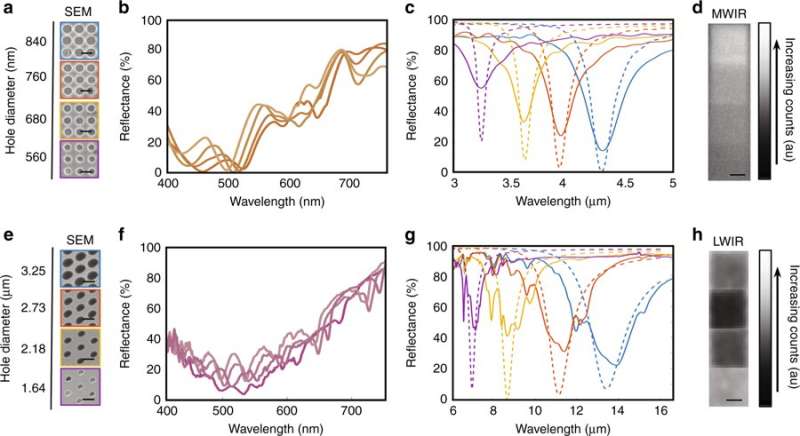
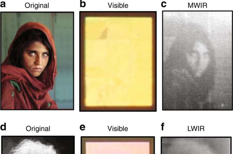
As a proof-of-principle, Franklin et al. encoded images and data onto material surfaces and observed them using infrared and visible cameras to demonstrate the potential of the cavity-coupled plasmonic system. In the technique, the scientists created a map between diameters of a given pixel and grayscale values of the surface to view through infrared camera imaging. The image was first encoded using direct laser writing onto a master template polymer that was used to fabricate the nanostructured surface using nanoimprint lithography (NIL). Before and after the NIL process the three-layered metallic cavities produced were imaged using scanning electron microscopy (SEM) for surface characterization.
By varying the laser writing parameters (power and speed) of the master writing process, the scientists obtained a variety of hole diameters for the mid-wave infrared (MWIR) and long-wave infrared (LWIR) devices. Depending on the angle of incident light and viewing angle, when viewed by the eye or using a visible regime camera, the encoded surface appeared as a uniform block of color. Meanwhile the infrared camera showed the encoded grayscale images at a resolution depending on the surface plasmonics.
The scientists conducted visible and infrared spectrometer measurements of the fabricated plasmonic systems. The infrared resonant surfaces were imaged using cameras designed for their respective bands of operation. A cooled indium antimonide detector was used to view the MWIR surfaces and an uncooled VOx microbolometer camera was used to view the LWIR surface. Dipolar coupling between the array of holes/disks and their interaction with optical cavity dictated the infrared response. Diffraction in to Fabry-Perot cavity modes dominated the visible regime. Grayscale images and data were encoded into the surfaces by mapping the diameter of holes of the plasmonic system to respective pixels.
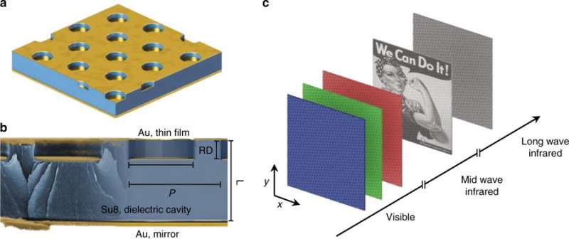
When the cavity-coupled plasmonic system was excited at resonance, coherent interactions between photons and the free electron density within the metal produced collectively charged oscillations known as surface plasmons. High-density charge localization and microcurrents resulted from the interactions on the edges of the metallic elements, whose energy dissipated by ohmic loss.
By varying the system's parameters, the scientists encoded images on the surface within a desired spectral range, while these images did not appear visible within others. For example, an image encoded within the mid-wave infrared (MWIR) window, appeared as a grayscale image when viewed through a MWIR camera, although the appearance within the visible range and long-wave infrared (LWIR) regime remained a constant color.
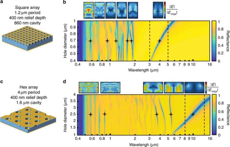
The scientists characterized optical traits of the cavity-coupled plasmonic system in the study and categorized them by geometrical features relative to the wavelength of incident light (λinc). To demonstrate this effect, two devices were primarily defined and simulated in the study led by the research group to operate in the MWIR and LWIR atmospheric transparency windows. The multispectral reflectance spectra of the respective surfaces were calculated as a function of the diameter of the hole using the FDTD method.
When the incident light was considerably larger than the pattern, the system behaved as a metallic plane or mirror. As the incident light decreased, extraordinary light transmission occurred through the subwavelength hole-disk array, due to induced plasmon resonance, coupling the electromagnetic wave into the cavity. As the incident light became comparable to the array's structural dimension, the system supported higher-order plasmonic and interference resonances due to the onset cavity-internal diffraction. Using the parameter study, Franklin et al. identified two possible routes to achieve infrared encoding; (i) the diameter of holes and (ii) the relief depth—while maintaining uniform visible absorption.
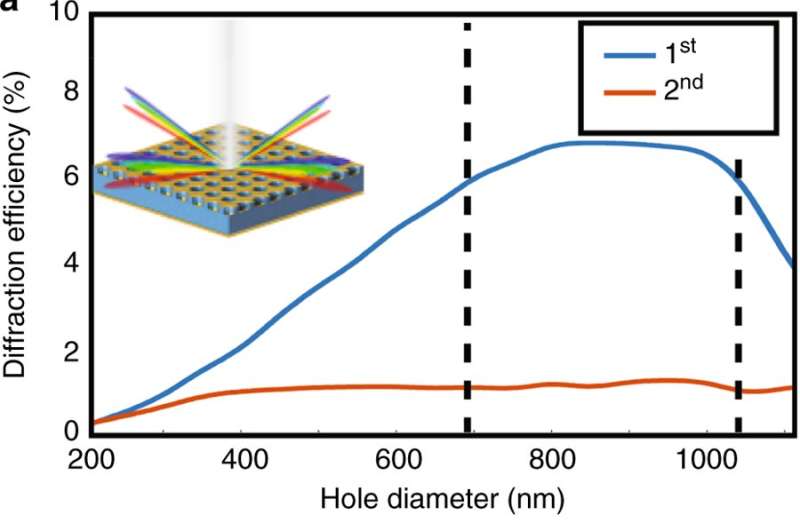
The scientists quantified diffraction efficiency in the study for the MWIR and LWIR devices as a function of hole diameter using FDTD. Results indicated that devices could be tuned for different wavelengths; primarily through the infrared transparency windows by modifying the hole/disk diameter and maintaining pixel-to-pixel brightness in the visible domain. The encoded information was not 'invisible' for different wavelengths, in contrast the dimensions of the plasmonic hole-disk system exceeded the diffraction limit of the visible light. Individual features were visible with high magnification objectives. The study combined ease of fabrication and compatibility on flexible substrates to engineer the device architecture. The results will lead to new plasmonic surfaces with multispectral functions to encode information.
More information: Daniel Franklin et al. Covert infrared image encoding through imprinted plasmonic cavities, Light: Science & Applications (2018). DOI: 10.1038/s41377-018-0095-9
Jon W. Stewart et al. Toward Multispectral Imaging with Colloidal Metasurface Pixels, Advanced Materials (2016). DOI: 10.1002/adma.201602971
Debashis Chanda et al. Coupling of plasmonic and optical cavity modes in quasi-three-dimensional plasmonic crystals, Nature Communications (2011). DOI: 10.1038/ncomms1487
Journal information: Light: Science & Applications , Nature Communications , Advanced Materials
© 2018 Science X Network


